

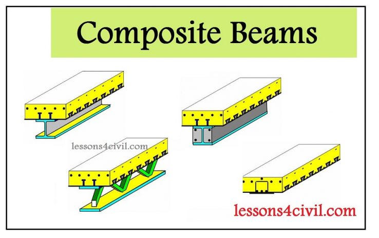
What is composite beam?
If the concrete floor is not attached to the underlying steel beams, floor and beams functions independently as a non-composite system. This way of design had been common for many years. However in the past decades, researchers found out if they design a sort of connectors between beams and concrete floors, the mechanical performance improves significantly. According the experimental results, the bearing capacity of beams which are attached to the concrete floor is 30 percent more than similar beams functioning independently.
Briefly, when steel beams are attached to the concrete paste the mechanical behavior of structure is improves. Moreover making such a composite material helps to reduce the amount of steel usage. The concrete coating will also protect the steel member against buckling, erosion and firing.
In this article I will explain the basic theory of designing steel-concrete composite members. If want to know more and master your designing skills, you can watch a video lesson provided for composite beam design.
Composite beam theory
Figure 1 shows a beam which is not attached to the concrete floor, while figure 2 illustrates a composite beam. As you can see when we attach the beam to the concrete the stress distribution becomes totally different. For figure 1, in the absence of any attachment, beam behaves as a non-composite member as if they are two separate bending members. Based on equilibrium principles C1=T1 and C2=T2. As a result the overall bending moment is equal to:
Mtotal = Mslab + Mbeam = C1d1+C2d2
On the other hand, in figure 2, we have a composite beam and there is no slippery between concrete and steel. As a result we have only one natural line and the overall bending moment is equal to:
Mtotal = Cd = Td
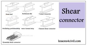
Shear connectors
To achieve a composite behavior, steel and concrete must be attached securely together. Shear connectors provides sufficient integrity to transfer shear stresses. There are several types of shear connectors including:
1- HEADED STUDS
2- PERFOBOND RIBS
3- T-RIB CONNECTOR
4- OSCILLATING PERFOBONDSTRIPS
5- WAVEFORM STRIPS
6- T-CONNECTORS
7- CHANNEL CONNECTOR
8- NON-WELDED CONNECTORS
9- INSA HILTI SHEAR CONNECTOR
10- PYRAMIDAL SHEAR CONNECTORS
11- RECTANGULAR-SHAPED COLLAR CONNECTORS
 Shear connectors connectors
In the future articles you will learn how to calculate the bending capacity of a composite beam.
Comments
ARSALAN114
How can perform fatigue analysis in abaqus
Vahid Shahraini
Hello my friend and sorry for delay in responding.
as you know fatige is about cycling loading. so first step is to learn about cycling loading in Abaqus. Fortunately, it has a new feature called Direct Cyclic procedure. The main advantage of this method is that we dont need to compute the number of sequential cycles that would lead to such stabilized cycle.
and another delicate thing about some analysis such as fatigue, is that you need to be very careful about element size. I suggest to start with a coarser mesh and after you make sure everything run smoothly make it finer. you can subscribe our youube channel : lessons4civil to get noticed of ever abaqus video clip we upload
Many thanks, Vahid Shahraini