

Braced Frame
As it is obvious, structures are always subjected to lateral loading such as wind load or earthquake. As a result the structure must be supported against lateral loading prevent any excessive deformation. A braced frame is a structural system to provide enough lateral stiffness for the building. These members are generally made of steel and have a significant tensile and compressive strength
Briefly, in a building beams and columns carry vertical loads, whereas bracing system resist against lateral loads. there are several technical considerations to position the braces. Moreover limitations such as the place of openings must be considered. A wise structural designer never choose the place of braces by chance. Each option has its own advantages and drawbacks. In our ETABS coarse we remind some optimization tips for selecting the right place of braces.
Compared to other methods such as shear wall, braced frame is more economical, easy to erect, less bulky. Moreover, using steel bracing the designer has more flexibility to meet the required strength and stiffness.
Different Bracing system
There are 2 general categories of braces:
Vertical braces are designed between column and in vertical planes. Using vertical braces is to transfer the lateral loads to the ground level. Each structure must be supported in both directions, so the minimum number of vertical braces is 2 brace in each plane. Based on the scope of plan and length of spans the number of braces can be reduced to 3 in total.
Horizontal bracing are designed in each floor in horizontal plane the main objective of horizontal braces is to transfer the horizontal forces to the planes of vertical bracing. Since the floor system can provide enough stiffness, the usage of horizontal braces are limited to certain conditions. Horizontal bracing is more popular in design of lightweight roofs that cannot provide enough lateral stiffness alone.
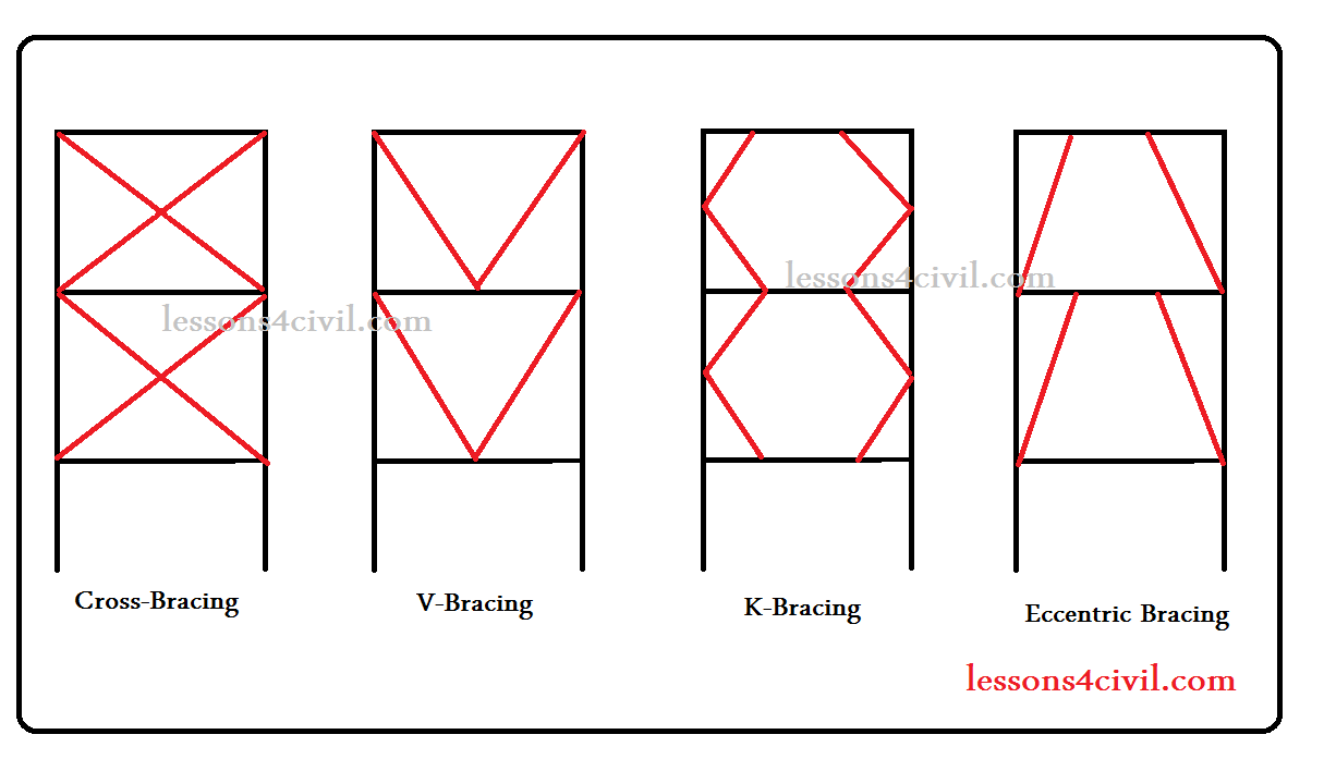
Bracing patterns
Bracing can be designed in different patterns including cross-bracing, K-bracing, V-bracing and Eccentric bracing. A summary of their technical differences is discussed in the following:
Cross-bracing
Cross-bracing, also known as X-bracing, is made of two diagonal members crossing each other. depending on the direction of loading one of these members act to resist sideways forces. Steel cables can also be used as cross-bracing.
K-bracing
These braces connect to the columns at mid-height. The geometry of K-braces gives the designer more freedom to place it around the openings. On disadvantage of K-bracing is its seismic response. In case of earthquake loading there is a high potential of compression buckling leading to failure of connected columns. So design of K-bracing is not recommended in seismic regions.
V-braces
Inverted V-bracing is another pattern which is made by two members meeting at a middle point of the horizontal member.
Eccentric bracing
Eccentric braces are highly recommended in seismic regions. Its general shape is similar to V-bracing. but there is a space between the bracing members at the upper connection point. This space between endpoints of the braces is called ‘Link’. This link area can act as an effective energy dissipator in case of earthquake loading. Actually when extreme seismic loading is applied, this area can deform non-linearly and absorb the excessive energy to protect the braces.
different bracing systems
Comments